Parameter configuration
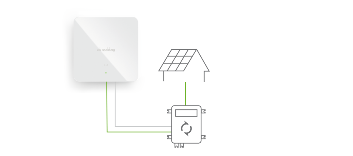
Configuration of solar power charging via potential-free enabling contact (Spelsberg Wallbox Smart Pro)
Before configuration in the Spelsberg Wallbox app can take place, the connection of a signal line to the potential-free contact of the PV inverter and the corresponding spring-cage terminals of the wall box is necessary. Further information and guidance on this can be found in the manual in Section 9.8 (Connection of the PV system signal line).
Once a connection has been established via the signal line, configuration by means of the Spelsberg Wallbox app can take place. To do this, open the app and go to System and then to Settings. Next click System integration and then Control via enabling contact. The following parameters must be set:
Parameter overview |
App Parameter | Settings |
Enabling contact | Activate (activation is only possible without dynamic load management) |
Logic behaviour of the external PV input | Selection (see table below for system states): |
Charging current when external PV input activated | Input (0.6 - 16 A) in 1 A steps |
Note: If the relay in the inverter is closed with the output active, then in this application the polarity should be set to "Active low". However, if the relay in the inverter is open then in this application the polarity should be set to "Active high". This depends on the execution in the inverter. An overview of how the system behaves is provided below.
In general, the polarity of the digital input must be correctly set as a function of the connected system and the application. The wallbox requires a potential-free contact for the digital input. As a rule, a relay is installed in the connected system (inverter, tariff changeover switch, home automation, etc.) which connects (NO) or opens (NC) two contacts when switching. These two contacts are connected to the PV1 and PV2 terminals of the wallbox using a signal line. Further information and guidance on this can be found in the manual in Section 9.8. The following table provides an overview of the various states:
System output Type | System output State | Polarity input 1 | Behaviour |
|---|
Normally Open | Off | Active High | Full charging current |
On | Charging current is reduced by the current offset |
Off | Active Low | Charging current is reduced by the current offset |
On | Full charging current |
Normally Closed | Off | Active High | Charging current is reduced by the current offset |
On | Full charging current |
Off | Active Low | Full charging current |
On | Charging current is reduced by the current offset |
The inverter must also have a setting for the value of the solar power or current beyond which the enable signal (known as a High Level) should be sent via the potential-free contact to the wall box, so that the wall box begins the charging process. This is the threshold that defines the on or off conditions and should be set somewhat higher than the charging current at the wall box.
Practical example:
The aim is that when sufficient solar power has been generated the wall box starts the charging process or stops it if insufficient solar power is available.
For this, the inverter requires a potential-free output (relay with NO contact). This output is configured in the inverter in such as way that it is open if there is no intention to charge or closed as soon as sufficient solar energy is available for charging. Both NO contacts of the potential-free output must be connected via terminals PV1 and PV2 to the Spelsberg Wallbox. For this a 2-wire cable with 0.5 mm² wires can be used.
To ensure that the charging process pauses when there is no signal from the inverter, the charging current must be set to 0A when the external PV input is activated. The logic behaviour is set to "Active low". In this example the following behaviour of the inverter applies: The relay in the inverter is open in the quiescent state (Normally Open), so that in the absence of a Signal (Off) the charging current is reduced to the stated value. If a signal is present (On), the contact closes and the charging process starts.
System output Type | System output State | Polarity input 1 | Behaviour |
|---|
| Normally Open | Off | Active Low | Charging current is reduced |
| On | Full charging current |